

The open area of perforated aluminium sheet is the area occupied by holes divided by the total area of the region being measured. Hole diameter describes one opening. To calculate an open-area percentage, you also need the centre-to-centre spacing and the pattern. Two sheets can both have 5 mm round holes, yet different spacing or layouts can put a different number of holes in the same area. Begin by defining which region you want to compare. That determines how the percentage should be calculated.
Distinguish hole diameter from centre-to-centre pitch
On a perforated aluminium sheet drawing, you may see d for the diameter of a round hole and p for the distance between neighbouring hole centres. Use the same units for both. The strip of metal between the edges of two holes is a different dimension. For equal round holes, measured on the line joining their centres, that strip is p − d. For example, a 5 mm diameter at an 8 mm pitch leaves 3 mm of metal along that line. This is a geometric result. Whether the width is suitable depends on the material, manufacturing process and application.
If horizontal and vertical pitches differ, record them separately. Indicate where the first row starts and how the rows are oriented relative to the sheet. This matters when the visual pattern has a preferred direction or holes need to line up across adjoining sheets. Identifying a reference edge and dimensioning the centre of the first complete hole from it makes it easier to compare the same feature on the drawing and the sample.
Calculate square pitch and 60° staggered patterns
For round holes on a straight square grid with equal horizontal and vertical pitch, the pattern open area is 78.54 × (d/p)² percent. For a 60-degree staggered pattern with equal nearest-neighbour pitch, the coefficient is 90.69. The round hole has the same area in both layouts. What changes is the repeat area associated with one hole. These coefficients apply to the stated patterns. For slots, square holes or unequal pitches, calculate the area of the opening and the repeat cell for that pattern separately.
At a 5 mm diameter and 8 mm pitch, the straight square pattern gives about 30.68% open area and the 60-degree staggered pattern gives about 35.43%. The diameter and pitch stay the same. Only the pattern changes. Keep the 5 mm diameter and the 60-degree pattern but increase pitch to 9 mm, and the open area falls to about 27.99%. These examples describe geometric proportions. They do not specify an achievable combination for a particular thickness or production line.
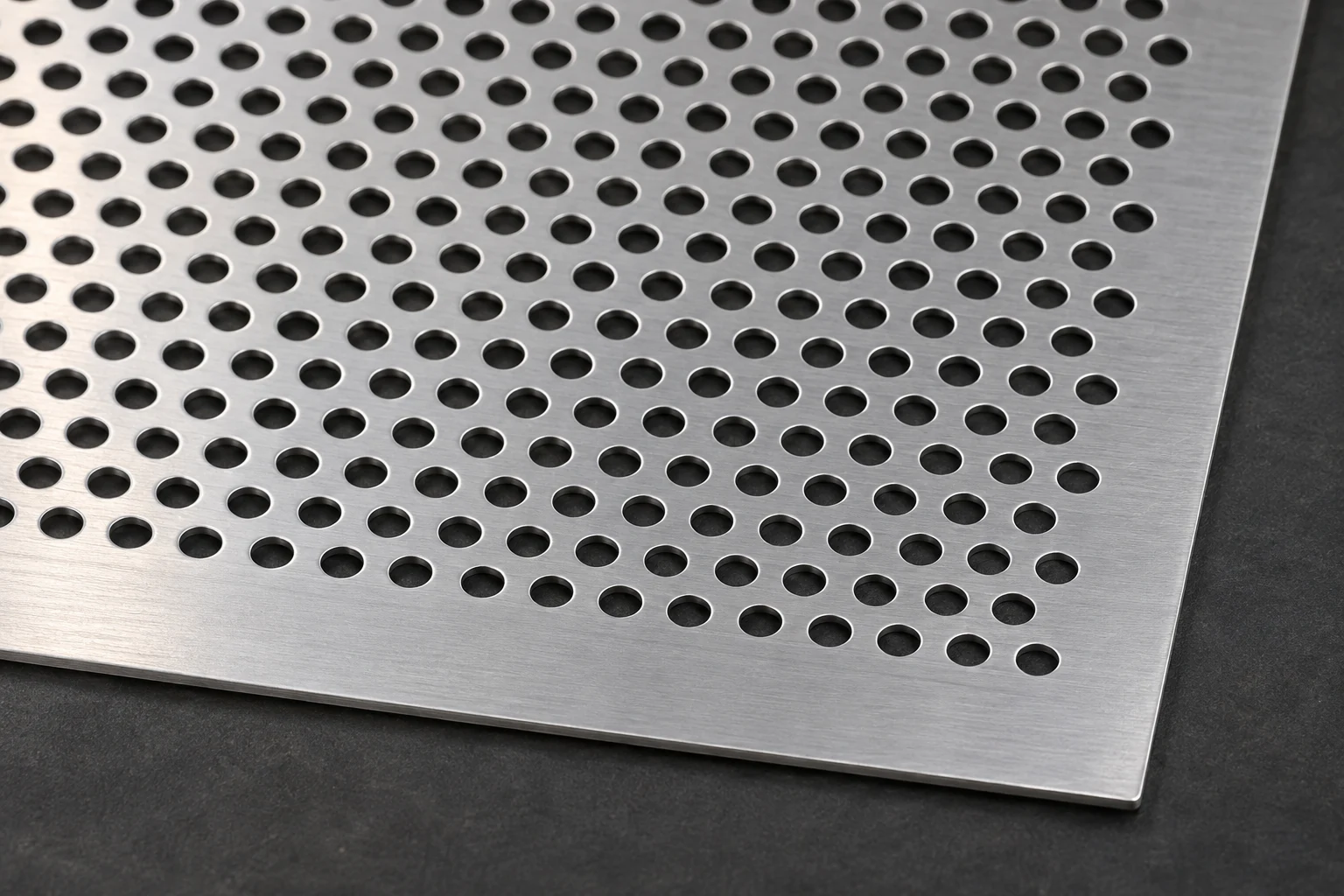
Separate the perforated field from the full panel area
The pattern formula describes a field with regularly recurring holes. A finished panel may have solid margins for fixing, blank zones or incomplete rows. If a field with about 35.43% open area occupies 80% of the total sheet area, the full panel has approximately 28.34% open area. That multiplication is a preliminary estimate based on a uniformly distributed pattern. Where missing repeats near the edges matter, sum the actual openings shown in the drawing and divide by the full panel area.
State which face and boundary define the calculation. If some openings are covered by another part after assembly, the area available to the design team can differ from the figure for the bare sheet. An explicit boundary gives the buyer, fabricator and installer the same reference. If a minimum percentage is specified for the whole panel, write down that the solid margins are included in the denominator.
Balance the application and manufacturing requirements
A higher open-area figure does not by itself make a design better. Rank the intended functions first, such as visibility, light, airflow or screening. Open area provides an initial comparison for a ventilation panel, while actual airflow also depends on geometry, installation and operating conditions. In a screening application, viewing angle, the distance to the surface behind the panel and lighting can change how open it looks. A percentage alone cannot validate the expected performance.
When discussing the perforated sheet service, use one drawing to record alloy, temper, thickness, hole diameter, pitch, pattern and edge margins. Include the overall dimensions and any bend lines. If holes pass through a bend zone or a row sits close to the edge, review those features before fabrication. Check the sample for hole diameter, pattern orientation and margins. Record which region the approved percentage refers to. If fabrication or installation changes, that note tells everyone which boundary to use when recalculating.
For a final check, put two differently sized parts in the same schedule. Show the pattern percentage and the finished-panel percentage separately for each. Even when the perforation is identical, an edge margin of fixed width can occupy a greater share of a smaller panel. The pattern percentage remains the same while the finished-panel percentage changes. This is worth checking at the drawing stage when one specification applies to several panel sizes.


